Навигация
Ceramic or Ferrites (BaFe203 or SrFe203)
60119
знаков
6
таблиц
15
изображений
2. Ceramic or Ferrites (BaFe203 or SrFe203)
A ferrite has a higher coercive force than Alnico, but at the same time has a lower remanent magnetic flux density. Their main advantage is their low cost and very high electric resistance.
3. Rare – earth (SmCO, NdFeb-Neodynium Iron Boron)
These are one of the strongest types of magnets available. They poses high remanent flux density, high coercive force, high energy product, linear demagnetization curve and low temperature coefficients. The main disadvantage is the cost.
High performance rare-earth magnets have successfully replaced Alnico and Ferrites magnets in all applications where the high power-to-weight ratio, improved dynamic performance or higher efficiency are of prime interest.
3.4.2 Factors affecting recycled magnets
The recycled magnets that will be used in this thesis were randomly picked; therefore there is no indication on how long they have been in the dumpsites. The following are the factors that can affect the strength of magnets:
· Heat
· Radiation
· Other magnets in close proximity to the magnet
If a magnet is stored away from high temperatures, and from the factors mentioned above, it will retain its magnetism essentially forever. Modern magnet materials lose a fraction of their magnetism over time if affected by the above factors [8].
3.5 Generator lossesThe losses in a synchronous generator consist of rotational loss (mechanical loss and magnetic loss) and copper loss in the armature winding. The rotational loss and the field winding loss are subtracted from the power to obtain the power developed by the armature. By subtracting the copper losses in the armature from the developed power, we obtain the output power of a synchronous generator.
In this section, the core loss will be discussed since they are due to the magnetic flux variations.
3.5.1 Eddy current lossThis power loss occurs in a magnetic core when the flux density changes rapidly in the core. Because core material has resistance, a power loss i2R will be caused by the eddy current and will appear as heat in the core [13].
The average eddy current loss is:
![]() (Eq. 3.3)
(Eq. 3.3)
where Pe is the eddy current loss in watts (W), ke is the constant that depends on the conductivity of the magnetic material, f is the frequency in hertz (Hz), δ is the lamination thickness in meters, Bm is the maximum flux density in tesla (T) and V is the volume of the magnetic material in cubic meters (m3) [14].
The eddy current losses can be reduced by [13]:
· Using a high-resistivity core material
· Using a laminated core, in transformers and electric machines the parts that are made of magnetic core and carry time-varying flux are normally laminated.
3.5.2 Hysteresis lossDuring a cycle variation of current i, there is a net energy flowing from the source to the coil-core assembly. This energy loss goes to heat the core. The loss of power loss in the core owing to hysteresis effects is called hysterisis loss.
By testing various ferromagnetic materials, Charles Steinmetz proposed that hysteresis loss can be expressed as [14]:
![]() (Eq. 3.4)
(Eq. 3.4)
where Ph is the hysteresis loss in watts, kh is a constant that depends upon the magnetic material and n is the Steinmetz exponent.
3.5.3 Core lossThe hysterisis loss and eddy current loss are lumped together as the core loss of the coil-core assembly, and given by:
![]() (Eq. 3.5)
(Eq. 3.5)
3.6 Design Variables
In the following section, all the parameters that are necessary to design and construct a generator will be discussed and variables such as generator diameter, length, etc. will also be calculated.
3.6.1 Speed of the generatorThe annual mean wind speed at Ga-Rampuru is approximately 4m/s [11]. The rotor will rotate at the same speed as the wind turbine; therefore this means that the rotor will rotate at:
![]()
![]() = 250 rad/s = 2387.3 rpm
= 250 rad/s = 2387.3 rpm
The rotor speed and the average frequency of the induced voltage are related by:
 (Eq. 3.7)
Since a two-pole machine will be designed, the frequency is calculated using equation 3.9 to be 39.79 Hz.
3.6.2 Rotor and Stator CoreA cylindrically shaped rotor will be appropriate for this design as it allows maximum flux distribution over the armature surface as the field coils are spread over the periphery of the rotor. This type of design also accommodates the use of small cylindrical magnets [11].
A low carbon steel core with low permeability will be used in this design as it was found in the recyclable materials found in the village. This type of steel is cheap and mostly available. Compared with other better and expensive steel such as silicon, cobalt, etc. this type of steel has a very high core loss. The steel saturation flux density Bsat is estimated from the BH curve to be 1.5T.
3.6.3 Rotor Diameter (D)The rotor diameter must be greater than the rotor yoke height (Hry), shaft radius (Rshaft) and the radial magnet length (Lm) [10].
D = 2 Hry + 2 Rshaft + 2Lm (Eq. 3.8)
In this design, D is restricted by the magnet arc radius of 25mm. Therefore D will be 50mm.
3.6.4 Rotor and Stator Yoke heightsThe minimum rotor yoke height Hry is the same as the stator yoke height Hsy. The height should be large enough to avoid saturation. This also has advantages of reducing core loss and reluctance.
The minimum yoke heights are given by [10]:
![]() (Eq. 3.9)
(Eq. 3.9)
The airgap length has a minimum value limited by the manufacturing tolerances; this value is typically in the range of 0.3mm to 1mm. In this design 0.5mm is chosen to be the airgap length.
3.6.6 Generator LengthThe generator length is estimated to be 95mm; this is approximated from flux required to give the output voltage of the generator.
3.6.7 Airgap Flux Per Pole
In a radial machine, the flux per pole is given by:
![]() (Eq. 3.10)
(Eq. 3.10)
where B is the average airgap flux density, D is the rotor inner diameter, L is the generator length, Kst is the lamination stacking factor and p is the pole pairs.
For this design the average flux density per pole Bgav is equal to the peak flux density Bg since the magnet arc is close to 180 degrees. Therefore the peak airgap flux is estimated to be 0.5T at the airgap and Kst is assumed to be 0.97.
The airgap flux and the lamination stacking factors were estimated from the following dimensions of the loudspeaker magnet:
· Magnet arc = 180 mechanical degrees
· Inner radius = 8mm
· Arc radius = 25mm
· Magnet radial length = 4mm
· Area of one pole = 706.8 μm2
From the above magnet dimensions, the flux per pole in the machine is then estimated to be 1.16 mWb this value is calculated from equation 3.10.
3.6.8 WindingsThe stators of most synchronous generators are wound with three distinct and independent windings to generate three-phase power [14]. A simple layer winding was used in this design. Slot per pole per phase was chosen to be 1 and the winding pitch was full pitch.
A. Types of winding
The preferred type of winding is distributed winding as it reduces harmonics and makes better use of the stator or rotor structure. The mmf induced in the airgap is not sinusoidal, to get a pure sinusoidal mmf the number of slots have to be infinity. This means that the distributed winding is expected to have some harmonics.
Induced voltage for the distributed windings is:
![]() (Eq. 3.11)
(Eq. 3.11)
Kw is the winding factor and depends on the winding arrangements and has a value less than unity. Distribution factor Kd and a short pitch factor Kp reduces the winding voltage magnitudes but also reduces certain harmonics in EMF and MMF waveforms.
![]() (Eq. 3.12)
(Eq. 3.12)
Distributed winding configuration has one slot per pole per phase and its winding factor is equal to 1.
B. Winding arrangement
Single layer winding, where each slot contains one coil side, will be used in this design as it is economical to manufacture and has simpler end connection. Emf and mmf can be modified to reduce harmonics. In a three phase system even harmonics do not appear due to the winding symmetry, the only visible harmonics are the belt harmonics.
C. Winding Pitch
Short pitch is the most commonly used type of winding pitch. It reduces the distorting harmonics and produces a truer sinusoidal wave. The length of the end connection is also reduced thereby saving copper and reducing copper loss in the coil.
The drawback of short pitch winding is that the induced emf in it is smaller than in a full-pitch coil. The reason is that the total flux linking the short-pitch coil is smaller than that of the full-pitch coil.
3.6.9 Number of turns
The number of turns per pole is estimated to be 60 turns from equation 3.11.
The design parameters discussed will be modelled in FEMM in the next chapter to induce the output voltage and flux of the generator.
Chapter 4. Modelling the design in FEMM 4.1 Introduction
The investigation that will follow focuses on the effect of substituting standard commercial magnets with recyclable speaker magnets that were collected from a dumpsite in the village, to compare the performance of the generator in either case.
In this chapter, the two pole generator geometry discussed in chapter 3 will be modelled in FEMM to analyse the output induced voltage and the flux of the generator. The lua-script in FEMM is run and the rotor is rotated 360 electrical degrees, for the lua-script refer to appendix C1.
Initially, a choice was made of three typical commercial magnet grades. Neodymium-iron-boron NdFeB was chosen from the rare-earth magnet group. Alnico6 was chosen from the Alnicos and the last type was barium ferrite from the ferrite or ceramic group. Then the machine will be modelled using different types of commercial magnets to investigate the performance of the generator.
The author then proceeded to investigate the magnetic properties of the loudspeaker magnet. This was done so that the parameters can be modelled in the finite element package.
Finally a design using the loudspeaker magnets was modelled to explore the recycled generator output.
4.2 Two pole geometryTable 4.1 below summarizes the generator specifications that were discussed in chapter 3. These parameters will be modelled in FEMM to view the output induced rms voltage and the flux.
| Quantity | Value |
| Frequency | 39.79Hz |
| Poles | 2 |
| Connection | Y |
| Diameter of Rotor | 50mm |
| Machine Depth | 15mm |
| Air gap length | 0.5mm |
| Turns per phase | 80 |
| Stator slots | 6 |
| Steel Core | 1020 steel |
Table 4.1 Data of designed PM machine
The design is modelled in FEMM and is illustrated in figure 4.1 below.
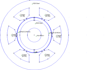
Figure 4.1 The generator modelled in FEMM
4.3 Commercial magnetsTo investigate the performance of the generator, the author began by modelling the generator with standard commercial magnets with the properties given in table 3.1. The output rms emf and flux of the generator is tabulated in table 4.2 with different magnets that were used in the design.
Refer to appendix B for the graphs of the outputs. Matlab soft ware was used to draw the output rms emf and the flux, matlab code included in appendix C2.
Table 4.2 Generator output with commercial magnets
| Magnet | Type | Flux (Rms) | EMF (Rms) |
| Rare-Earth | NdFeb32 | 0.0459 | 9.4262 |
| Alnico | Alnoco6 | 0.0186 | 5.1619 |
| Ceramic | Ceramic8 | 0.0175 | 3.6075 |
The magnet that was used in this section was from a loudspeaker that was found lying in one of the dumps at Ga-Rampuru village. To start with the magnet shape was not of concern. The author aimed to investigate the performance of the magnet on the speaker if used as it was found. The properties of this magnet were investigated and a design was modelled using these magnets. The magnet is shown below in figure 4.2.
4.4.1 Background on the characteristics of loudspeaker magnetsFor speaker applications, the amount of permanent magnet required is directly proportional to the rated output power of the speaker. In other words high power speakers are often made using the high-grade magnetic types like the rare-earth. But since the speakers found in the dumpsite were from low power appliances their typical magnets are normally from the ceramic group type. In addition unlike Alnico magnets, ferrite or ceramic magnets are not easily demagnetised magnetized and hence find wide application in such appliances.
Похожие работы


... OF GEORGIA JSC – Valuation (Refer to Annex 1) Valuation Limits True Value (GEL mln.) True Value/Market Cap. Low 50.8 3.3 High 68.6 4.4 4.3 Human-Resource Development in the Private Sector 4.3.1 Business Schools/Universities European School of Management (ESM). Data Sheet. European School of Management ESM-Tbilisi 40, Vazha ...

... . Зав. кафедрой -------------------------------------------------- Экзаменационный билет по предмету НЕМ. ЯЗ. ФРАЗЕОЛОГИЯ Билет № 16 Дайте определение понятия «язык». Что считает О. Бехагель «первородными классами слов» немецкого языка? Кто и в каком году опубликовал первый сборник общераспространенных немецких поговорок? К какому типу устойчивых словосочетаний согласно ...
... 's journal, A Voz de Timor, patronized by the government. He and intellectual Domingos de Oliveira were custom officials. Cesar Mouzinho was Mayor of Dili. ASDT/Fretilin (Revolutionary Front of Independent East Timor). The plan of ASDT was acknowledged in the proper day of it's foundation, 20th of May. Adopting the doctrines of socialism and democracy it called upfront for a gradual independence ...
... is so attractive to developing countries. Furthermore, many of the hotel and restaurant jobs are semiskilled work, so only a small amount of training is necessary to fill them. 2. Tourism in Spain 2.1 Useful information about Spain If you are coming to Spain for the first time, be warned: this is a country that fast becomes an addiction. You might intend to come just for a beach ...
0 комментариев